

Manufacturing Solution
Sheet Metal Fabrication
CNC laser cutting, punching, press brake forming, hardware insertion, welding and finishing for custom enclosures, brackets, panels and frames.
- Processes
- Laser cutting, punching, CNC bending, hardware insertion, welding and coating as scoped
- Typical materials
- Cold rolled steel, 304/316 stainless, 5052/6061 aluminum, copper and brass, subject to review
- Order size
- Prototypes to recurring production, subject to capacity review
- Documentation
- Flat-pattern review; FAI, coating report and CoC when specified
- Delivery
- Protective packaging, palletizing and freight terms agreed per project
Versatile sheet metal enclosures and components
Sheet metal fabrication turns flat stock into enclosures, chassis, brackets and frames through cutting, forming, joining and finishing. For suitable designs and volumes, it can avoid the dedicated die investment associated with stamping.
Early drawing review considers flat patterns, bend allowances, hole-to-bend clearances, hardware access and weld requirements. The proposed route and inspection criteria are agreed before production release.
- Prototype and recurring runs without dedicated stamping dies where suitable
- CNC cutting and press brake forming for custom geometry
- Hardware insertion, welded assemblies and protective finishes as scoped
Integrated fabrication capabilities
The operations are selected and sequenced around the drawing, material and order requirements.
- 01
Precision flat cutting
Fiber laser cutting or turret punching can produce blanks, holes and internal profiles. Nesting and edge requirements are reviewed for the material and part.
- 02
CNC press brake forming
Bend sequence, tooling, back-gauge access and critical angles are established from the approved flat pattern.
- 03
Hardware insertion
Self-clinching nuts, studs or standoffs can be installed at a suitable stage, subject to sheet grade, thickness and clearance.
- 04
Welding and mechanical joining
MIG, TIG or spot welding, where suitable, is planned around joint access, fixtures and drawing-defined inspection criteria.
- 05
Surface finishing and assembly
Deburring, blasting, graining, powder coating or other material-compatible finishes can be included with specified sub-assembly work.
Fabrication stages
Illustrative views of typical equipment and outcomes; the manufacturing route is confirmed per project.
-
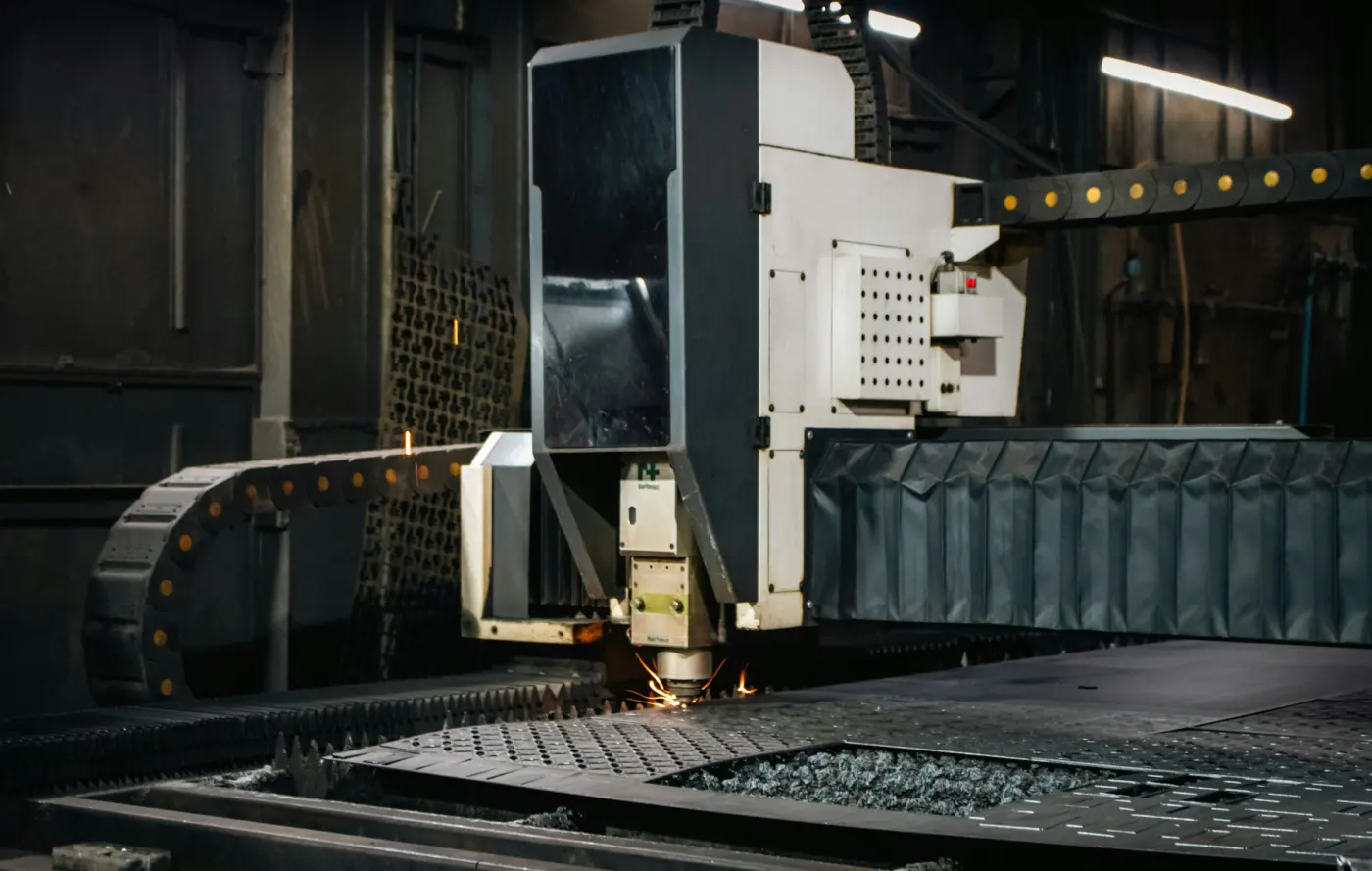
CNC laser cuttingFlat blanks and cut features are planned from approved files. -
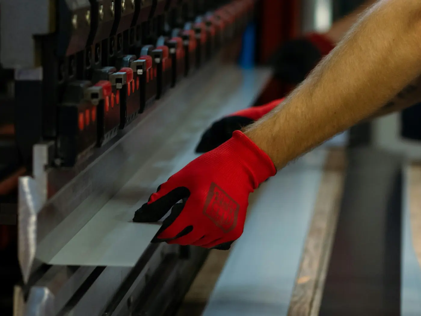
Press brake formingBend tooling and sequence follow the part geometry. -
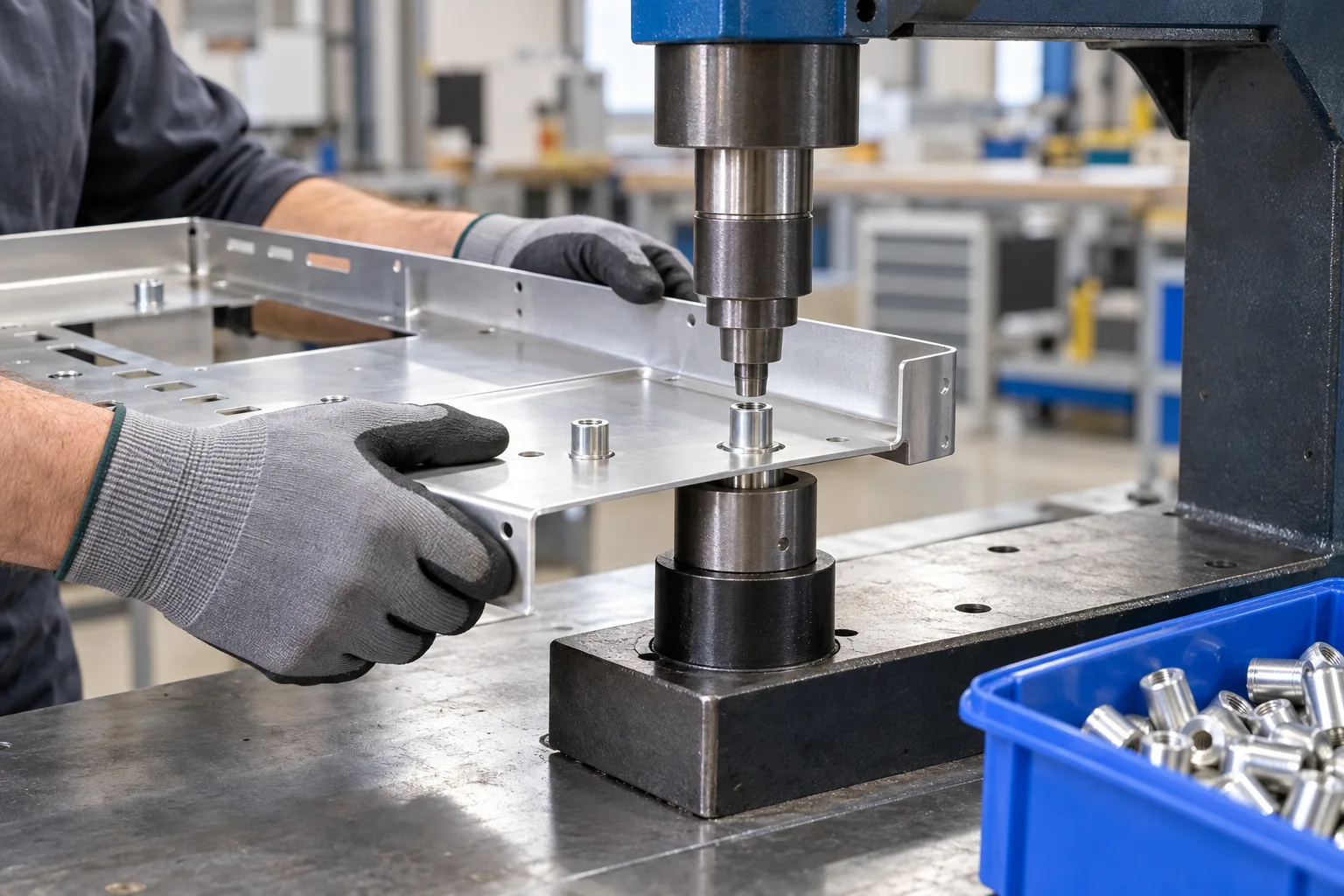
Hardware insertionInsertion access and sheet compatibility are checked in the route. -
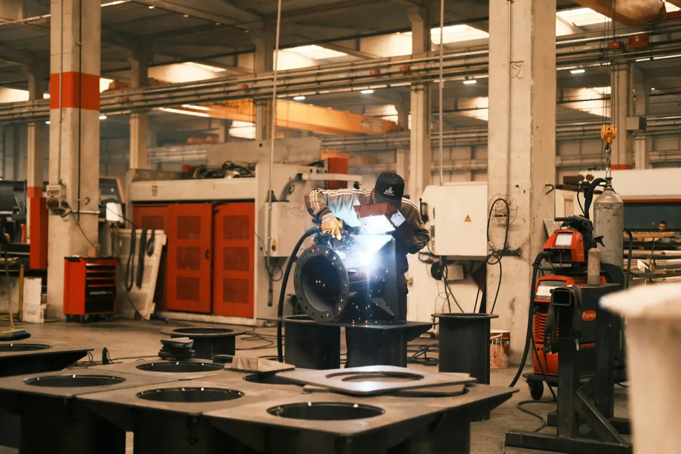
Welding and joiningThe joint and inspection requirements are set by the drawing. -
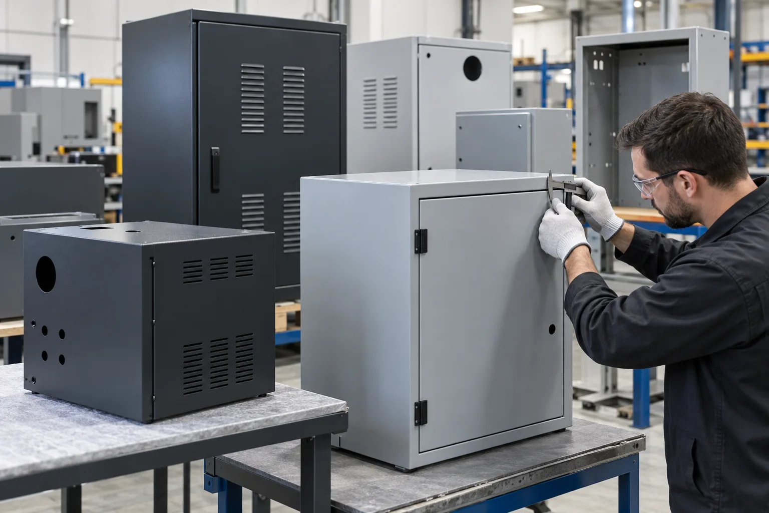
Finished enclosuresCoating and final checks are defined for the application.
Scope and specifications
The quotation confirms feasible processes, material options, tolerances and documentation.
- Core operations
- Laser cutting, punching, bending, hardware insertion, welding and finishing as applicable
- Materials
- Carbon and stainless steel, aluminum, brass and copper, subject to process review
- Thickness range
- Evaluated by material grade, part geometry and forming limits
- Tolerances
- Critical cut and formed dimensions agreed from the drawing and selected process
- Finishes
- Powder coating, wet paint, plating, anodizing, passivation or screen printing where material-compatible and available
- Lead times
- Schedule confirmed after drawing, material, quantity and finish review
Design for manufacturability guidelines
Use these as review starting points; final dimensions depend on the material and tooling.
Keep bend radii consistent
Uniform inside radii can reduce press brake setup changes. A radius near the sheet thickness is a common starting point, subject to alloy and grain direction.
Allow hole-to-bend clearance
Keep holes and cutouts clear of bend deformation. Twice the thickness plus the bend radius is a starting guide, not a universal minimum.
Add bend reliefs
Relief slots at flange corners can limit tearing and unwanted distortion during forming.
Specify standard hardware
Use catalog self-clinching fasteners where they suit the sheet thickness, hardness and installation access.
Define weld requirements
Mark weld locations, structural requirements, visible surfaces and acceptance criteria on the drawing so finishing effort can be planned.
Sheet metal questions
What files are useful for a quotation?
A 3D model and drawing with material, thickness, finish, tolerances and quantity are useful. A flat DXF can also help, but the final flat pattern is reviewed against the bending route.
What tolerances can fabricated parts hold?
Cut and formed dimensions vary with material, thickness, bend sequence and datum scheme. Mark critical dimensions and angles for a process-specific review.
When might stamping be a better option?
For stable designs and recurring higher volumes, a stamping route may justify tooling investment. The crossover depends on geometry, volume and lifetime demand.
Can an existing color or finish be matched?
Provide a color reference, gloss or texture target, and any approved sample. The coating process and acceptance method are confirmed during quotation.
How are welding standards handled?
State the applicable code, weld callouts and inspection needs. Facility qualifications and the proposed welding route are reviewed before the order.
Can finished assemblies include hardware?
Hardware, hinges, gaskets and other components can be reviewed for inclusion in an assembly quoted under one part number.
Have a fabricated part to source?
Share the drawing, material, expected quantity and finish requirements so we can review the route and quotation scope.
Related pages

Laser Cutting
Fiber laser profile cutting for sheet, plate and tubular parts, with scope reviewed per project.
Learn more
Metal Stamping
Metal stamping and custom die tooling for repeat components and production programs.
Learn moreSheet Metal Materials
Compare stainless, aluminum and carbon steel grades by typical properties.
Learn more
Surface Finishing
Compare metal finishes by base metal, thickness and callout.
Learn more